

How PDC Drill Bits Are Made: Inside the PDC Bit Manufacturing Process
From formation analysis and cutting-structure design to CNC machining, cutter brazing and final inspection
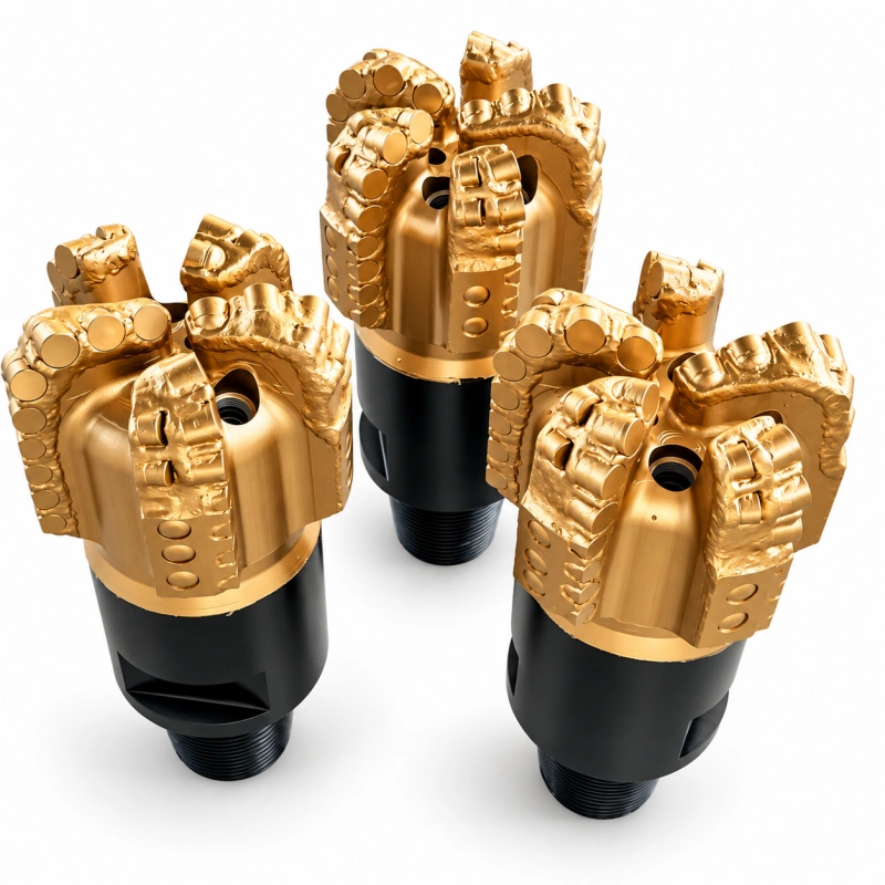
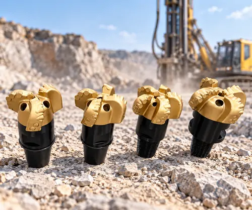
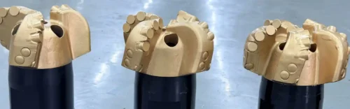
A finished PDC drill bit may look simple: a steel body, several blades, a number of PDC cutters, waterways and a threaded connection. However, behind that finished tool is a manufacturing process where small differences can have a big effect on field performance.
Cutter position, blade shape, brazing quality, gauge diameter, waterway sizes, thread accuracy and wear protection — any of these can affect penetration rate, drilling stability, bit life and the customer’s drilling cost.
Because of this, we believe making a PDC bit should not start with machining steel. It should start with understanding the drilling job. In short, a good PDC bit is not just made to a diameter. It is designed around the formation.
Quick summary: PDC bit manufacturing runs from formation analysis and cutting-structure design to CNC machining, cutter brazing, wear protection, gauge control and final inspection. In short, consistency across batches matters as much as any single step.
What Is a PDC Cutter?
Before talking about how a PDC bit is made, it helps to understand the cutting element at the heart of the tool. PDC stands for Polycrystalline Diamond Compact.
A typical PDC cutter has two main parts:
- Polycrystalline diamond layer
- Tungsten carbide substrate
The diamond layer gives an extremely hard, wear-resistant cutting surface. Meanwhile, the carbide base gives mechanical support and lets the cutter be attached firmly to the bit.
During drilling, the PDC cutter removes rock mainly by shearing. Instead of relying on repeated crushing like a roller cone bit, the fixed cutters shear rock continuously as the bit turns. As a result, PDC bits can reach strong penetration in suitable formations.
However, cutter quality alone does not decide drilling performance. The cutter must also sit in the right place and be supported by a well-designed bit structure.
Step 1: Understanding the Drilling Application
Before production starts, the first step should be understanding where and how the bit will be used. For custom PDC bits, key information includes:
- Required bit diameter
- Formation type
- Formation hardness
- Formation abrasiveness
- Drilling depth
- Drilling application
- Drill rig
- Rotary speed
- Torque
- Flushing method
- Required connection
For example, two customers may both need a 152 mm PDC bit. One may be drilling fairly soft mudstone. The other may be drilling abrasive sandstone mixed with limestone. Although the diameter is the same, the right cutting structures may be very different.
Because of this, our first question should not simply be “what diameter do you need?” It should also be “what are you drilling?”
Step 2: PDC Bit Design and Cutting-Structure Planning
Once the drilling conditions are clear, the next stage is design. Important design elements include:
- Bit profile
- Blade number
- Blade shape
- PDC cutter size
- Cutter quantity
- Cutter position
- Cutter exposure
- Cutter angle
- Waterways
- Junk slots
- Gauge structure
- Connection
These items decide how the bit meets the formation.
Blade Number
Different PDC bits may use 3-wing, 4-wing, 5-wing, 6-wing or other custom setups. Fewer blades usually give more open space between cutting structures. This can help cuttings flow out and can give a more aggressive cut in suitable formations.
More blades let more cutters spread around the face and may improve load spread and stability. However, extra blades also take up space. Therefore, more blades do not automatically mean a better bit. The blade setup must be chosen for the formation.
Step 3: Planning the PDC Cutter Layout
Cutter placement is one of the most important parts of a PDC bit. A professional bit is not designed by simply spacing cutters at equal distances.
Cutters at different radial positions work under different conditions. For example, a cutter near the outside diameter travels farther in each turn than a cutter near the center. As a result, cutter speed, workload and wear can differ across the face.
The cutting structure needs to think about:
- Radial cutter position
- Cutting speed
- Cutter exposure
- Back rake
- Cutter size
- Formation hardness
- Abrasiveness
- Impact load
- Load spread
The goal is to spread the cutting work well while keeping drilling stable. Poor cutter layout can lead to:
- Uneven wear
- Cutter overload
- Too much torque
- Vibration
- Lower penetration rate
- Early cutter failure
In short, cutter layout should be treated as an engineering decision, not just a manufacturing step.
Step 4: Selecting the Bit Body
Modern PDC bits are usually made with either steel-body or tungsten-carbide matrix-body construction. These two structures behave differently.
Steel-Body PDC Bits
Steel-body PDC bits are machined from suitable alloy steel. Their main advantages include:
- High structural toughness
- Good machining freedom
- Precise blade shapes
- Large potential junk-slot area
- Flexible waterway design
- Easier customization
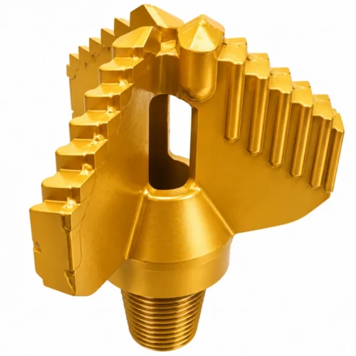
Steel-body structures are especially useful for many water well, mining, geothermal, construction, grouting, anchor and non-coring PDC jobs. However, steel itself is less abrasion-resistant than matrix material. Because of this, wear protection may be added to critical areas.
Matrix-Body PDC Bits
Matrix-body PDC bits use a tungsten-carbide-based composite around an inner steel structure. Their main strength is resistance to abrasion, erosion and fluid wear. Therefore, matrix structures can help in tough abrasive conditions.
However, matrix material is usually more brittle than steel. So the bit shape must account for these material traits. In short, neither structure is always better. The right body depends on the drilling job.
Step 5: Raw Material Preparation
For a steel-body PDC bit, suitable alloy steel is chosen based on the required structure and mechanical properties. Before machining, the raw material must leave enough allowance for:
- Blade machining
- Cutter pockets
- Waterways
- Gauge section
- Thread connection
- Other structural features
Material consistency matters, because the body must handle torque, axial load, vibration, impact, abrasion and repeated loading. In short, the body is the base that supports the whole cutting structure.
Step 6: CNC Machining the Bit Body
After the design is confirmed, the steel body enters machining. CNC machining is used to create the main structural features, which may include:
- Blade shape
- Cutter pockets
- Junk slots
- Waterways
- Gauge section
- Internal passages
- Connection features
Precision at this stage is very important. Even a small size error can affect cutter position, blade symmetry or final gauge diameter.
For repeat orders, CNC machining also helps improve batch consistency. A customer who orders the same bit again should not receive a very different cutting structure just because the production date changed. In short, consistency is part of quality.
Step 7: Machining the Connection
The connection between the bit and drill string is a critical structural joint. Depending on the job, common connections may include:
- 2 3/8 REG
- 2 7/8 REG
- 3 1/2 REG
- 4 1/2 REG
- NC23
- NC26
- NC31
- NC38
- Z-50
Other connections can also be reviewed to customer requirements. The connection must be made accurately, because wrong thread shape can cause:
- Hard assembly
- Poor load transfer
- Early thread wear
- Connection damage
- Drilling safety problems
For custom products, customers can send drawings, samples or exact thread specs.
Step 8: Cutter-Pocket Preparation
Every PDC cutter needs a properly prepared seat or pocket. The pocket controls:
- Cutter position
- Cutter angle
- Cutter exposure
- Mechanical support
- Brazing area
If the pocket is inaccurate, even a top-quality cutter may not work as planned. Because of this, pockets should be checked and prepared before cutter fitting. This is an important change from machining to assembly.
Step 9: PDC Cutter Selection
Different drilling conditions may need different PDC cutter specs. Factors to consider include:
- Cutter diameter
- Diamond-table traits
- Impact resistance
- Wear resistance
- Thermal performance
- Formation traits
Common PDC cutter sizes used in different tools may include:
1304 · 1305 · 1308 · 1613
However, cutter choice should not be based on size alone. A larger cutter does not always mean longer life. Likewise, using more cutters does not always mean better performance. The cutter grade and cutting structure need to work together.
Step 10: PDC Cutter Brazing
Cutter fitting is one of the most sensitive stages in making a steel-body PDC bit. The cutters must be fixed into their design positions while keeping accurate:
- Orientation
- Exposure
- Angle
- Position
A brazing alloy is used to create a strong joint between the tungsten-carbide base of the cutter and the prepared pocket. Temperature control matters a lot here.
The brazing process must give enough heat to make a strong joint, while avoiding needless heat damage to the PDC cutter. Important factors include:
- Surface prep
- Brazing material
- Heating control
- Brazing temperature
- Heating time
- Cutter position
- Cooling method
In short, a good-looking braze does not always mean a strong joint. Process control is what matters.
Why Brazing Quality Is So Important
During drilling, PDC cutters face heavy forces. They see cutting force, torque, vibration, impact, heat and abrasive contact. If the attachment is weak, the cutter may come loose or fail early. This can lead to:
- Loss of drilling efficiency
- Damage to nearby cutters
- Unbalanced drilling
- Shorter bit life
Because of this, cutter brazing should be treated as a critical manufacturing step, not just assembly.
Step 11: Hardfacing and Wear Protection
Steel-body PDC bits give strong structural toughness and design freedom. However, the steel body itself can still face abrasion and erosion. Because of this, selected areas may get extra wear protection.
Depending on the design, this may include hardfacing, tungsten-carbide elements, wear-resistant materials and extra gauge protection. Critical wear zones can include:
- Blade surfaces
- Shoulder areas
- Gauge pads
- Fluid-exposed surfaces
The goal is not to cover the whole bit with wear-resistant material. Instead, it is to protect the areas most likely to face damaging contact or erosion.
Step 12: Gauge Protection
The gauge section controls the final borehole diameter. During drilling, this area stays in contact with the borehole wall. If the gauge wears too much, the bit may start drilling undersize.
This can create problems for hole quality, drill-string movement, later tools and overall drilling efficiency. Because of this, gauge protection may include:
- PDC elements
- Tungsten-carbide inserts
- Wear-resistant hardfacing
- Reinforced gauge structures
In short, the exact design should depend on formation abrasiveness and drilling conditions.
Step 13: Waterway and Cuttings-Evacuation Design
A PDC bit does not only need to cut rock. It must also remove the broken rock. This makes waterway design very important.
During drilling, fluid should help:
- Clean the cutters
- Cool the cutting structure
- Carry cuttings
- Reduce recutting
- Reduce bit balling
- Keep the bottom of the hole clean
If cuttings cannot escape well, drilling performance may drop even when the cutters are still sharp. The operator may see:
- Lower penetration
- Rising torque
- Cutter overheating
- Bit balling
- Too much recutting
In short, large, well-placed junk slots can be very useful in suitable steel-body PDC designs. Hydraulics and cutting structure should be treated as one system.
Tip: In many projects, poor cuttings flow is mistaken for a dull bit. In other words, check waterway shape and junk-slot size before blaming the cutters.
Step 14: Dimensional Inspection
After the main manufacturing steps are done, the bit should be checked for size. Important measurements may include:
- Outside diameter
- Overall length
- Connection sizes
- Cutter position
- Cutter exposure
- Blade sizes
- Gauge sizes
- Waterway sizes
For custom products, these values should be checked against the confirmed drawings or technical requirements. The goal is simple: make what was approved — not something roughly similar.
Step 15: Cutter and Brazing Inspection
Every cutter should be checked by eye for:
- Correct position
- Surface condition
- Brazing quality
- Abnormal movement
- Damage
The cutting structure should also be checked for overall balance and consistency. This step matters a lot, because one badly placed or weakly attached cutter can affect the whole bit.
Step 16: Thread and Connection Inspection
The thread connection should be checked before shipment. Depending on the requirements, checks can include:
- Thread form
- Sizes
- Surface quality
- Fit
- Connection condition
The connection should also be protected before transport to avoid accidental damage. In short, a high-quality bit can still become unusable if the thread is damaged during shipping.
Step 17: Surface Finishing and Corrosion Protection
After inspection, the finished bit can be cleaned and finished. For steel-body products, suitable surface protection can help reduce rust during storage, sea transport, warehouse handling and international shipping.
Depending on the product, protective finishing may include:
- Cleaning
- Surface treatment
- Protective coating
- Paint
- Anti-rust protection
The goal is not just looks. A product that may spend weeks in international transport needs to arrive at the customer’s site in good shape.
Step 18: Final Quality Control
Before shipment, the complete bit should go through a final check. Our QC approach focuses on several basic questions:
- Is the diameter correct?
- Is the connection correct?
- Are the cutters in the right position?
- Is the cutting structure consistent with the approved design?
- Is the gauge structure complete?
- Are the waterways clear?
- Is the body free from obvious defects?
- Is the thread protected?
- Is the product ready for international transport?
Only after these checks should the bit move to packaging.
Step 19: Packaging for International Shipment
PDC cutters resist wear very well in rock, but the cutting edges should still be protected from uncontrolled impact during transport. Because of this, packaging should protect:
- PDC cutters
- Thread connections
- Gauge structure
- Finished surfaces
Depending on bit size and shipping method, packaging may involve:
- Protective covers
- Internal cushioning
- Cartons
- Wooden cases
- Export packaging
International customers may receive their tools after long road, air or sea transport. Therefore, packaging is the final part of manufacturing quality.
Manufacturing Quality Is About Repeatability
One good drill bit can be made by chance. Manufacturing quality means something different: it means producing the next batch with the same critical traits.
Customers who reorder drilling tools expect:
- The same diameter
- The same connection
- The same cutting structure
- The same cutter spec
- Similar manufacturing quality
- Predictable field performance
Because of this, drawings, size records and standard production steps matter. In short, repeatability builds long-term customer trust.
How Chenghui Manufactures Customized PDC Drill Bits
Not every drilling project can use a standard catalogue product. Because of this, our PDC bits can be reviewed against customer requirements. Customization may include:
- Outside diameter
- Blade quantity
- PDC cutter spec
- Cutter quantity
- Cutter layout
- Bit profile
- Waterway setup
- Gauge structure
- Thread connection
- Overall sizes
- Application-specific reinforcement
Customers can provide technical drawings, existing drill bits, product photos, used-bit photos, formation information and rig specs.
Our goal is not simply to copy the look of an existing tool. Whenever enough drilling info is available, we prefer to understand why the previous bit performed the way it did before setting the new setup.
From Used Bit to Improved Bit
A worn drill bit can give very useful engineering information. For example:
| Wear Sign | Possible Meaning |
|---|---|
| Broken PDC cutters | Impact load, vibration or formation change |
| Heavy shoulder wear | Abrasive rock or too much load concentration |
| Gauge wear | Not enough wear protection |
| Uneven cutter wear | Unstable drilling or uneven cutter load |
| Packed material between blades | Poor cuttings flow or bit balling |
Customers with drilling problems can send us clear photos of the used bit. These wear patterns can help guide the next design.
Why Manufacturing Process Matters to the Customer
A customer does not buy CNC machining, brazing, hardfacing or quality inspection. The customer buys meters drilled. Everything in the manufacturing process should serve that goal.
Accurate cutter placement can improve load spread. Reliable brazing can reduce early cutter loss. Proper waterways can improve cleaning. Gauge protection can keep hole size. Accurate threads can ensure a reliable drill-string joint.
Because of this, quality manufacturing is not about making the bit look better in a photo. It is about helping the bit perform steadily underground.
Frequently Asked Questions
How is a PDC drill bit made?
The process starts with formation analysis and cutting-structure design, then moves to CNC machining, cutter-pocket preparation, PDC cutter brazing, hardfacing, gauge protection, dimensional and brazing inspection, surface finishing and final QC before packaging.
Why does cutter brazing matter so much?
Because PDC cutters face heavy cutting force, torque, vibration, impact and heat during drilling. If the braze is weak, the cutter may come loose or fail early, which damages nearby cutters and shortens bit life.
What is the difference between steel-body and matrix-body PDC bits?
Steel bodies give high toughness, flexible blade shapes and larger cuttings channels. Matrix bodies resist abrasion and erosion better. Because of this, the right body depends on the formation and drilling system, not on a single “best” material.
Why is repeatability important in PDC bit manufacturing?
Because repeat customers expect the same diameter, connection, cutting structure and performance in every batch. Repeatability — not one-off quality — is what builds long-term customer confidence.
What information should I send for a custom PDC bit?
Send diameter, formation, application, drilling depth, thread connection and rig model. If possible, also send rock photos, core samples, existing bit photos, worn-bit photos and technical drawings.
Conclusion: From Design to Delivery, Built for Real Conditions
Modern PDC bit manufacturing combines material selection, cutting-structure design, precision machining, cutter installation, wear protection, hydraulics and quality control. Every stage affects final performance.
Our approach is simple: understand the application, design for the formation, manufacture with consistency and inspect before shipment.
Whether you need a PDC bit for water wells, geological exploration, mining, geothermal drilling, anchor drilling, grouting, foundation work or a custom project, send us your drilling information before production. In short, a high-performance bit begins long before it reaches the rig — with the right design and a controlled manufacturing process.
Looking for a custom PDC drill bit built for your formation? Send us your drilling conditions and our team will review the cutting structure, brazing and wear protection before production.
Share your diameter, formation, application, drilling depth, thread and rig model. Photos of rock, core samples or worn bits also help a lot.







 English
 Chinese
 Portuguese
 French
 Spanish
 Russian
 Turkish
 Vietnamese